How to Make Remote Removable
How to Make a Cable
Note: There is a sticker in your conference bag with an ethernet pinout as well!
How to Test a Cable
How to Modify the 555 timer Circuit
The badge uses a 555 timer in an astable configuration to create a pulse that in turn increments the 4017, such that a new line of the LAN cable is tested. More details on the about page. When the 555 timer is in an astable circuit, the output voltage alternates between high and low on a continuous basis, without any interaction. This oscillation is controlled by the values of 3 passive components: 1 capacitor and 2 resistors. Varying these parts will make it oscillate faster or slower! Here is an astable configured circuit:
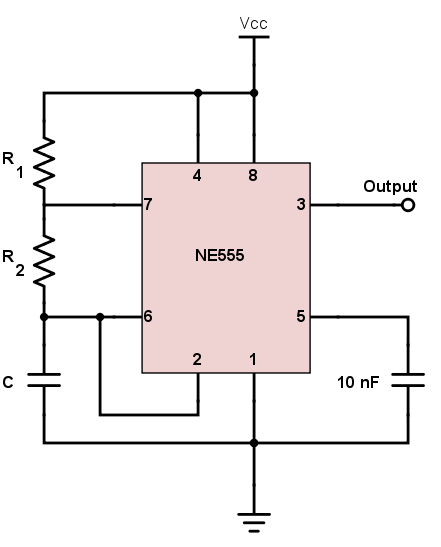
Using the schematic on the about page and the interactive BOM (or your badge), can you figure out which components on the badge control the oscillation?
Click for Answer
R1, R2, and C2 are the components on the back of the badge, at the top!
Using the interactive BOM, can you figure out their values?
Click for Answer
R1 = 10k Ω, R2 = 150k Ω, and C2 = 4.7 uF
Scour the web to find a 555 astable calculator. Can you use it to figure out how fast the pulse should be with those values? You may need to do some SI unit conversions depending on the calculator!
Click for Answer
roughly 1 hz... aka about a half second on and off, with one full cycle taking 1 second
You now should have a decent understanding how the 555 timer is configured on your badge! Play with the calculator you found to theoretically see how fast or slow you could get your badge to oscillate!
Enough theory... now's the time to do it for real! Head over to the hardware hacking village if you are not already there!
First decide what changes you are going to make using your 555 calculator. Creativity and experimentation with the calculator can limit how many parts you need to remove/add. Work with the village volunteers to verify we have the parts you want to use before preceding! You may need to change your plans depending on what is available. Don't start removing things until you have the replacement parts in hand. These are the capacitors and resistors the village has.
With your parts in hand, you can now remove the parts you want to change. Before you start, ensure your badge is OFF or remove the battery! The badge uses surface mount parts. To remove, use a globular amount (technical term) of solder on your iron, such that both soldered ends of the part you wish to remove are being touched/heated by the glob. Then simply swipe the part off! More than likely the small part is stuck on the glob on the iron, have tweezers ready to flick it off. Or use a tip cleaning sponge to remove.

Now its time to add the new part! For ease, these parts are through-hole parts. They are meant to go through holes on the PCB (printed circuit board), but for our purposes we will be soldering them to the surface mount pads. Bend and trim the legs of your new part such that they are well positioned for both sides of the surface pads. You can make this as tidy or as messy as you want! Solder one leg. Now readjust the second leg, and solder it! Booya! New part is on!
Now repeat the process for all the parts neccesary for your plan!
All done? Turn your badge on and bask in the glory of your newly modified badge! Pretty cool huh? Nice work!
I hear there is a CTF challenge that has something to do with the 555 timing circuit...